Choosing the right thermowell is more than selecting a fitting for a temperature sensor. It is a decision that affects measurement accuracy, mechanical integrity, process safety, and long-term reliability.
In industrial temperature measurement, the wrong thermowell can lead to inaccurate readings, vibration-induced sensor failure, a liberated thermowell, unscheduled outages, or even a breach of the primary pressure boundary. A properly selected thermowell must protect the sensor, withstand process conditions, and meet the requirements of the application.
This guide walks through the key factors engineers, maintenance teams, and field operators should consider when selecting a thermowell for an industrial process.
A thermowell is a protective fitting installed into a pipe, vessel, or process system to shield a temperature sensor from direct contact with process media.
Instead of inserting the temperature sensor directly into the process, the sensor is placed inside the thermowell. This allows the sensor to measure temperature while being protected from pressure, corrosion, erosion, flow forces, and mechanical damage.
Thermowells are commonly used with temperature sensors such as thermocouples and RTDs. They also allow technicians to remove or replace the sensor without opening the process line, which improves safety and reduces maintenance complexity.
A properly selected thermowell must support accurate and repeatable temperature measurement while protecting the sensor and maintaining the integrity of the process connection.
The first step in choosing a thermowell is understanding the process conditions.
Temperature and pressure influence the thermowell’s:
A thermowell used in a low-pressure water line will not have the same requirements as one used in high-pressure steam, chemical processing, refining, or natural gas service.
The right thermowell must balance three critical requirements: accurate temperature measurement, mechanical integrity, and compliance with ASME PTC 19.3 TW.
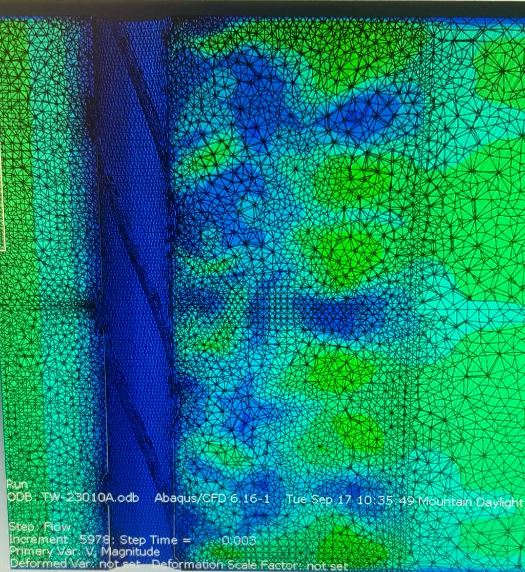
Flow velocity is one of the most important thermowell selection factors, especially in piping systems with moving fluids or gases.
When process media flows around a thermowell, alternating vortices can form behind the stem. This is called vortex shedding. If the vortex shedding frequency aligns with the thermowell’s natural frequency, the thermowell can begin to vibrate. This condition is known as vortex-induced vibration, or VIV.
If not properly addressed, VIV can create fatigue damage over time. In severe cases, it can lead to sensor failure, thermowell breakage, or loss of containment.
Improper thermowell design can create three major risks:
This is why wake frequency calculations are essential in flowing applications. These calculations help confirm whether the thermowell can safely withstand the process conditions before installation.
Material selection should be based on the process media, operating temperature, pressure, corrosion risk, and mechanical requirements.
Common thermowell materials include:
The material must be compatible with the process. Choosing the wrong material can shorten service life, increase maintenance needs, or compromise the reliability of the temperature measurement system.
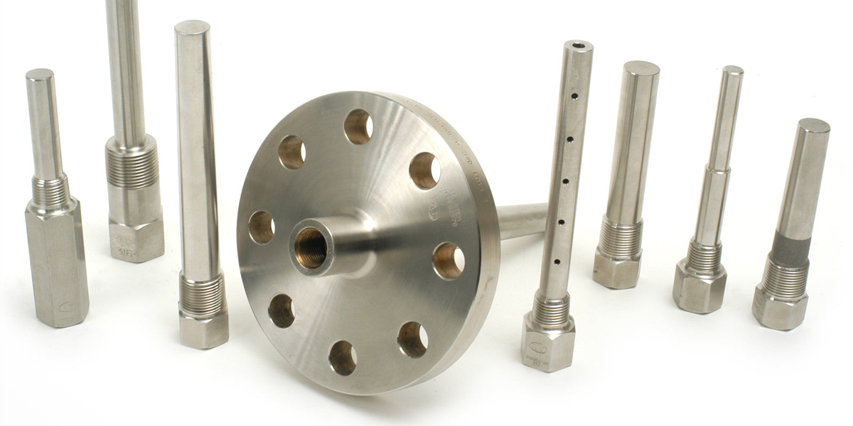
The mounting connection determines how the thermowell is installed into the pipe or vessel. The most common thermowell mounting options are threaded, flanged, and weld-in connections.
Threaded thermowells are often used in smaller lines or less severe applications. They are relatively easy to install and remove, but may not be suitable for every high-pressure, high-temperature, or high-vibration environment.
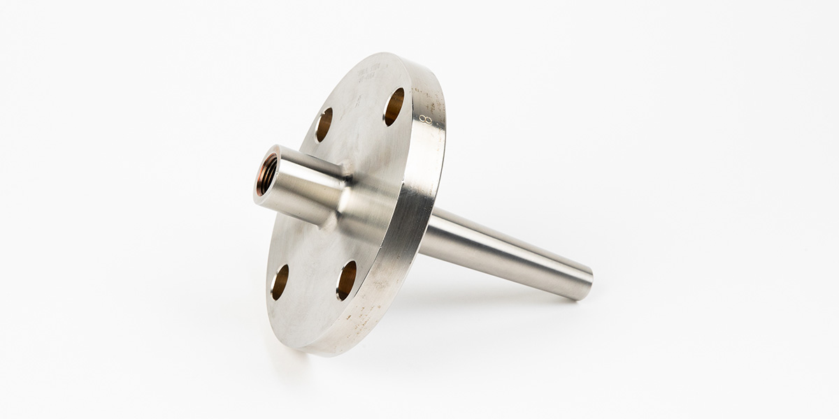
Flanged thermowells are commonly used in higher-pressure or more critical applications. They provide a strong mechanical connection and are often preferred where inspection, removal, and replacement are important.
Weld-in thermowells provide a permanent connection to the process. They are often used where leak prevention, strength, compact design, or severe service performance is a priority.
The best connection type depends on the process conditions, maintenance requirements, piping design, and applicable site standards.
Insertion length, often called U-length, is the distance from the thermowell connection point to the tip of the thermowell.
This matters because the sensor must reach a representative area of the process stream to provide an accurate reading. If the thermowell is too short, the sensor may be influenced by pipe wall temperature rather than true process temperature. If it is too long, it may create unnecessary mechanical stress and increase the risk of vibration.
As a general positioning strategy, the thermowell tip should protrude more than one-third of the way into the process piping. Ideally, the tip should be positioned near the centre of turbulent flow for accurate and repeatable measurement. For immersion depth, a common guideline is 5x the root diameter for liquid applications and 10x the root diameter for gas applications.
Lagging extensions may also be required when insulation is present around the pipe or vessel.
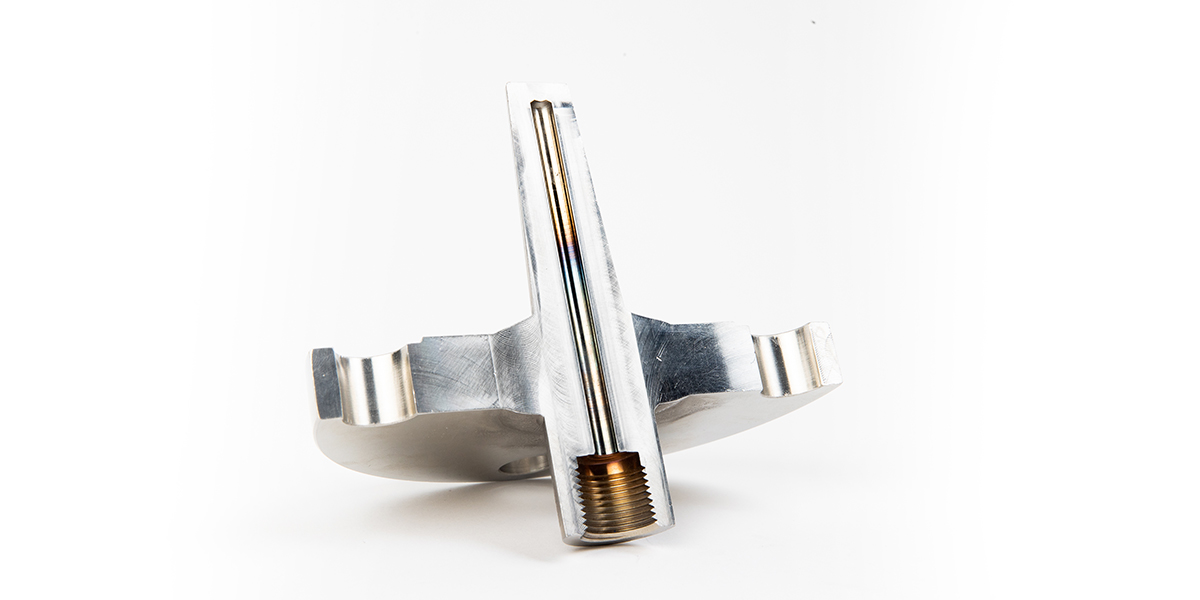
The stem, or shank, profile affects strength, response time, and vibration resistance.
Straight thermowells have a consistent diameter along the stem. They are simple and commonly used, but may be less suitable in some higher-velocity applications depending on process conditions.
Tapered thermowells are thicker at the root and narrower toward the tip. This profile can provide improved strength and vibration resistance, making it a common choice in more demanding flow applications.
Stepped thermowells have a reduced tip diameter. This can improve response time because there is less material at the sensing end. However, mechanical strength and wake frequency performance must still be carefully evaluated.
The stem profile should never be selected based on response time alone. It must also be evaluated for pressure, flow velocity, vibration resistance, and mechanical integrity.
For thermowells installed in flowing process media, ASME PTC 19.3 TW is the key standard used to evaluate thermowell mechanical suitability.
A wake frequency calculation is used to determine whether the thermowell can safely operate under the expected process conditions. The required inputs typically include:
A thermowell must meet specific quantitative criteria to be considered acceptable. If the calculation fails, design changes may be required, such as:
In simple terms, a thermowell should not be considered suitable simply because it fits the pipe. It must also survive the process conditions.
Aircom manufactures thermowells and protection tubes for industrial temperature measurement applications, with options designed to meet customer specifications and demanding process conditions.
Aircom’s thermowell and protection tube capabilities include:
For high-temperature applications where conventional alloy thermowells are not suitable, Aircom also manufactures protection tubes designed to protect temperature devices in more extreme service conditions.
For applications where vortex-induced vibration is a concern, Aircom offers the StrakeWell, a specialized thermowell designed with helical strakes to suppress VIV on thermowell shanks. Helical strakes help address two major wake frequency calculation challenges: frequency limit and dynamic stress limit.
The goal is simple: help customers achieve accurate, reliable temperature measurement without compromising mechanical integrity.
Learn more about Aircom’s Thermowells and Protection Tubes
Thermowell selection should be treated as an engineering decision, not a simple accessory purchase.
To choose the right thermowell, consider:
The most common mistake is focusing only on fit while overlooking flow, vibration, material compatibility, and mechanical integrity.
A properly selected thermowell protects the temperature sensor, supports accurate readings, improves maintainability, and reduces the risk of mechanical failure. A poorly selected thermowell can create risk for operations, maintenance, engineering, HSE, and the wider facility.
A thermowell protects a temperature sensor from direct contact with process fluids, pressure, corrosion, and flow forces while allowing the sensor to measure process temperature.
Wake frequency is important because flowing media can create vortex-induced vibration. If vibration becomes severe, it can cause fatigue damage or thermowell failure.
ASME PTC 19.3 TW is the standard used to evaluate thermowells installed in flowing media. It helps determine whether the thermowell can withstand process conditions such as pressure, temperature, velocity, density, and viscosity.
The best material depends on the process. Stainless steel is common for general use, while Inconel, Hastelloy, Monel, and other alloys may be required for high-temperature, corrosive, or aggressive applications.
Straight thermowells have a constant diameter, tapered thermowells provide added strength at the root, and stepped thermowells can improve response time at the tip. Each must be evaluated against process conditions.
Insertion depth depends on the pipe size, sensor type, and process conditions. A common guideline is to place the tip more than one-third into the process piping, with immersion depth of 5x the root diameter for liquids and 10x the root diameter for gases.
Flanged thermowells are commonly used in higher-pressure, critical, or industrial applications where a strong process connection and serviceability are required.
A StrakeWell is Aircom’s specialized thermowell design that uses helical strakes to help suppress vortex-induced vibration and improve thermowell performance in challenging flow conditions.